Logic Gates and Truth Tables Explained for Beginners
Computers are complex machines that can do math faster than any person.
But what makes computers able to compute? The answer lies in how logic gates work.
Logic gates are the fundamental building blocks of digital circuits. They turn Boolean logic into real world signals that are able to make the computers we have today. Understanding how logic gates work can better help you understand how computers work.
Logic Gates and Truth Tables Basics
Digital logic gates manipulate Boolean values using logical operations, or Boolean logic. To generalize boolean logic, any input for boolean values can either be "yes" or "no", "true" or "false". There is no in between like "maybe". With logic gates and digital computers:
- "1" is equal to "true"
- "0" is equal to "false"
This is called true/false logic. To answer how logic gates work, Boolean logic is important to understand. Let's learn about what the NOT gate is and how it connects to Boolean logic.
The NOT Gate Explained
The NOT gate takes 1 input, which, as explained earlier, can be either a "1" or a "0". The NOT gate inverts the input:
- Inputting a 1 outputs a 0
- Inputting a 0 outputs a 1
The NOT gate itself is pretty self-explanatory, but in more complex circuits with hundreds of inputs and outputs, you will want an easier way to visualize what a circuit does. This is called a truth table.
Truth table for a NOT gate:
| Input A | Y (NOT A) |
|---|---|
| 0 | 1 |
| 1 | 0 |
There's one input labeled "A" and one output labeled "Y". When A equals 1, Y equals 0, and so on. This greatly simplifies explaining all the inputs and outputs of logic gates. The NOT gate also has a symbol used in schematics or logic diagrams when designing a logic circuit.
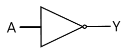
The NOT gate is symbolized by a triangle pointing to the right with a small circle at the output. The circle indicates inversion, or that the output is the opposite of the input. The input in the gate's visual is labeled A, and the output is labeled Y. These are the labels that indicate which column in the truth table corresponds to which pin on the logic gate. When we look at the inputs and outputs of the AND gate, we have double the inputs, thus doubling the different combinations able to occur on the gate.
AND Logic Gate Explained

| Input A | Input B | A AND B |
|---|---|---|
| 0 | 0 | 0 |
| 0 | 1 | 0 |
| 1 | 0 | 0 |
| 1 | 1 | 1 |
The AND gate outputs true only when both inputs are true. If just one of my inputs is false, output false. An easy way to remember what the AND gate does is that it checks if both inputs A AND B are true. The AND gate symbol is also included in the image. As you can see, the second input is called B, which corresponds to the second column on the truth table. The AND gate symbol has a flat left side for the inputs and a curved right side for the output.
AND Gate Example
Let's say you were designing a safety for a rocket launch system. If you wanted to make sure the rocket wasn't launched accidentally, you could use an AND logic gate to check if the user is pressing the button AND the safety switch is turned on as well.
NAND Logic Gate Explained
| Input A | Input B | A NAND B |
|---|---|---|
| 0 | 0 | 1 |
| 0 | 1 | 1 |
| 1 | 0 | 1 |
| 1 | 1 | 0 |
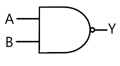
The NAND gate includes a small output circle, just like the NOT gate, indicating inversion. If you take a glance at the truth table, the outputs are exactly the opposite of the AND gates. NAND stands for "not AND," or the inverse of the AND gate.
OR Logic Gate Explained
| Input A | Input B | A OR B |
|---|---|---|
| 0 | 0 | 0 |
| 0 | 1 | 1 |
| 1 | 0 | 1 |
| 1 | 1 | 1 |
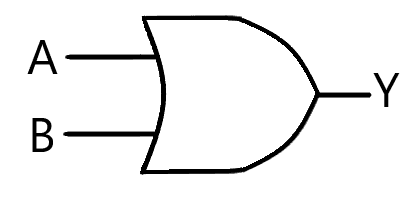
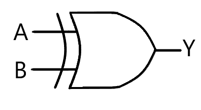
The OR gate symbol looks similar to the AND gate, but it curves outward on the input side and comes to a point at the output. The OR gate takes two inputs, and if A or B is true, then the output is true.
OR Gate Example
If you were designing a fan to keep you cool during the summer, you could use an OR gate that turns on a fan when the temperature gets to be too hot OR when the humidity level rises too much.
NOR Logic Gate Explained
| Input A | Input B | A NOR B |
|---|---|---|
| 0 | 0 | 1 |
| 0 | 1 | 0 |
| 1 | 0 | 0 |
| 1 | 1 | 0 |
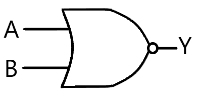
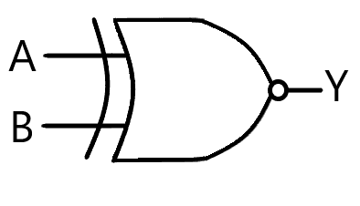
NOR, like NAND, means "not OR," and its inputs are completely reversed from the OR's. The only time the NOR is true is if none of the inputs are true.
XOR Logic Gate Explained
| Input A | Input B | A XOR B |
|---|---|---|
| 0 | 0 | 0 |
| 0 | 1 | 1 |
| 1 | 0 | 1 |
| 1 | 1 | 0 |
The XOR and XNOR gates resemble the OR gate symbol but with an additional curved line on the input side, distinguishing them as 'exclusive' gates.
The X in XOR stands for exclusive. The XOR gates output a 1 if the two inputs are not the same and a 0 if the inputs are the same. These gates are mainly used for adding two numbers together. XOR gates are used in binary addition because they determine the sum bit without carry.
If you're adding two bits, A and B, the sum bit is the corresponding row on the truth table for A and B, and the carry-out bit is an AND operation on A and B. The logic for the lower two bits would look like the XOR's truth table.
XOR Gate Example
An XOR gate can detect when two buttons are pressed differently. This is useful in some game controllers where only one input should be active at a time, not both.
XNOR Logic Gate Explained
| Input A | Input B | A XNOR B |
|---|---|---|
| 0 | 0 | 1 |
| 0 | 1 | 0 |
| 1 | 0 | 0 |
| 1 | 1 | 1 |
Like the NAND and AND gates, the XNOR is "exclusive not or," and its outputs are inverted (given by the circle on the output).
Conclusion
Logic gates aren't just concepts. To get a better grasp on how logic gates work, I recommend building your own logic gates with transistors. You can also buy your own logic gates and use them on a breadboard circuit.
Logic gates are essential components in digital electronics, forming the foundation for all computing devices.
People Also Ask
About the Author
This article was written by Boden Bensema, an electronics hobbyist focused on teaching beginner-friendly circuit design, breadboarding, and electronics fundamentals.
About page